Topology Optimization of a Compliant Gripper
Anthony Klepacki
Advisor: Professor Kai James
Problem Formulation
The purpose of the project is to optimally design a compliant gripper mechanism using topology optimizations. A compliant mechanism is unique in that all motions and transfer of motion in the mechanism is due to elastic deflections. The fixed design domain in which we want to optimally distribute material is shown in Fig.1. The other design specifications considered are a thickness of 1 cm, a Young’s modulus of 11 MPa and a Poisson’s ratio of 0.4. The compliant gripping mechanism will be 3-D printed from FLX9895DM and must satisfy the geometrical boundary conditions as specified in the figure and must be able to hold a minimum of 4 lbs.
The first step in order to optimize the workspace is to solve the forward problem (FEA) . Due to the shape and boundary conditions of the domain, to perform the FEA we first took advantage of the planar symmetry of the problem, shown in Fig.2. Planar symmetry allows us to save computation time, which is reflective of the number of degrees of freedom (DOF). Thus, by doing half symmetry we achieve a cost saving factor of 4 (global system is n × n).
When performing planar symmetry, to solve the FEA problem we must constrain the bottom surface of the new domain, shown in Fig.2, in the vertical direction allowing the structure to move in the horizontal direction. A gripper mechanism like pliers has symmetric input forces and output forces and through compliance the mechanism clamps down on the open location to exert a force.
The desired location of output for our given gripper mechanism is located at the right end. The mechanism inverts the direction of the input force. There are generally two methods to optimize the mechanical advantage: in Method 1 the output degree of freedom is fixed, while in Method 2 a spring of fixed spring constant, Ks, is presented at the output degree of freedom to express the reaction force as Fout = −Ksuout, where uout is the expected output displacement at the output node as shown in Fig.3b.
We used Method 2 with a force of 10 N over 2 cm and a spring constant of 200 Nm.
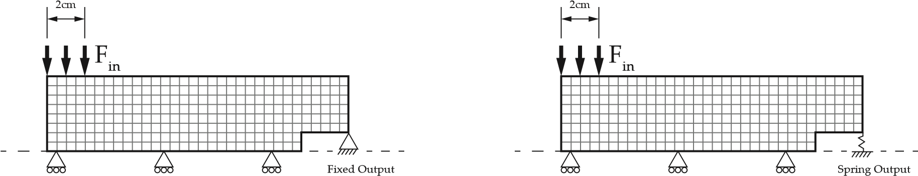
(a) Method 1: Fixed Output (b) Method 2: Spring Output
Figure 3: Two different modelling approaches
The elastic displacement of any point in the domain is determined by the geometry, loading, boundary conditions and material properties as stated above and now we may perform finite element analysis to solve for the displacement. Modelled in 2-D linear-elastic elements, the mesh size of the structure was varied in order to determine various optimized configurations, using a four-node quadrilateral element. The global force vector is defined by the applied loads and the degrees of freedom where it is applied. Due to the structures internal degrees of freedoms being free from the applied load their respective force is set to zero. For our case, the applied force is applied to the degrees of freedom at the top of the structure.
We formulated the objective function as shown in Eq.(2), trying to minimize the ratio of the mechanical advantage since the output force is in the opposite direction of the applied force (resulting in a negative value for mechanical advantage). The objective function is subject to a volume constraint and compliance constraint.
The design domain is discretized with finite elements (Fig.4) and the volumetric density ‘ρi’ of each element is used as the design variable. The SIMP method was used as the penalization model. The material property of each element used to determine the FEA solution is expressed by
E = ρpE0
where E0 denotes the Young’s modulus of the material and ‘p’ is the penalty exponent. In our optimization solutions, p = 3 is used.
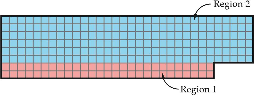
Figure 4: Mesh Generation
From the problem formulation for the design of a compliant mechanism, the mechanism should effectively convert the applied input force into a desired output force. The design domain, boundary conditions, and loads were specified to carry out the FEA and then the elemental sensitivities will be calculated from the solutions of the forward problem.
Solution
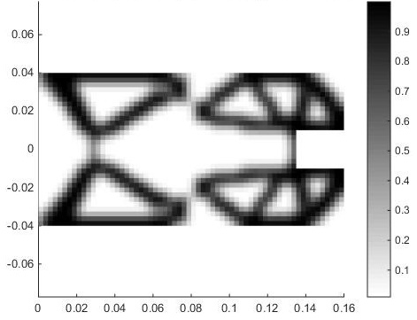
Selecting the parameters for the optimization problem was a trial-and-error process. Since the design space is littered with thousands of local minima, precise qualitative assertions on the selection of the parameters was not possible. However, it is interesting to note the variety of converged solutions that were obtained from varying the problem parameters. Fig.5 shows some of the solutions that resulted from parameter variations.
The parameters that were varied are:
-
Volume fraction (Vmax)
-
Filter radius
-
Spring stiffness at the output (Ks)
-
Maximum allowable compliance (Cmax)
-
Mesh size
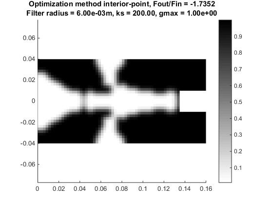
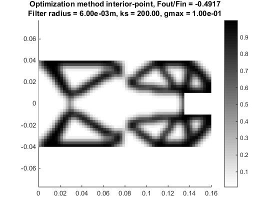
Fig.5a shows the structure obtained from eliminating the volume constraint entirely. Fig.5b shows the typical checkerboarding pattern obtained from setting a zero-filter radius. Fig.5c shows a converged result with a different maximum allowable compliance. Fig.5d shows a slightly different structure (notice the hinge) obtained from reducing the spring stiffness the output. Finally, Figs.5e and 5f used the same parameters except for the mesh size. The finalized structure that we chose to print was the one obtained with the finer mesh. This was the structure that yielded the highest mechanical advantage, so naturally it was the local optimum that we chose. The parameters used to obtain this result were the following:
-
Volume fraction (Vmax) = 0.4
-
Filter radius = 0.006 m (≈ 4 elements)
-
Spring stiffness at the output (Ks) = 200 N/m
-
Maximum allowable compliance (Cmax) = 1 Nm
-
Mesh size = 128×32 (half problem)
(a) Volume Fraction (b) Checkerboarding
(c) Compliance change (d) Spring stiffness change
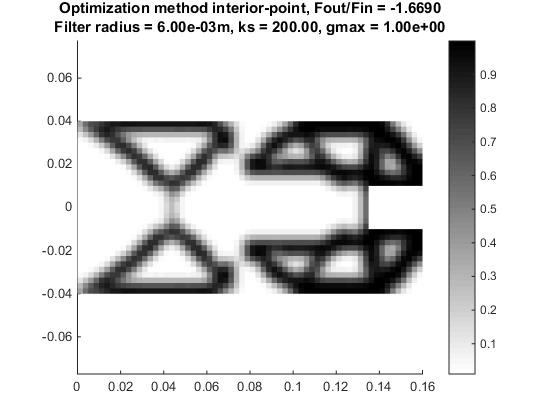
(e) Coarse mesh (64×16) (f) Fine mesh (128×32)
Figure 5: Various structures obtained by changing problem parameters
Failure Analysis
The material layout obtained by the optimization procedure (Fig.5f) was converted into a 3-D CAD model. This model was used to produce the compliant mechanism via 3-D printing. The same model was also used to perform Finite Element Analysis using ANSYS software. The result of the optimization procedure is a coarse representation of the optimal structure. ANSYS was used to perform stress analysis rather than our code because it represents the actual structure that will be produced. The ability to simulate an unstructured mesh with many elements at low computational expense makes a commercial software the best choice for the purpose of analyzing the stress in the part.
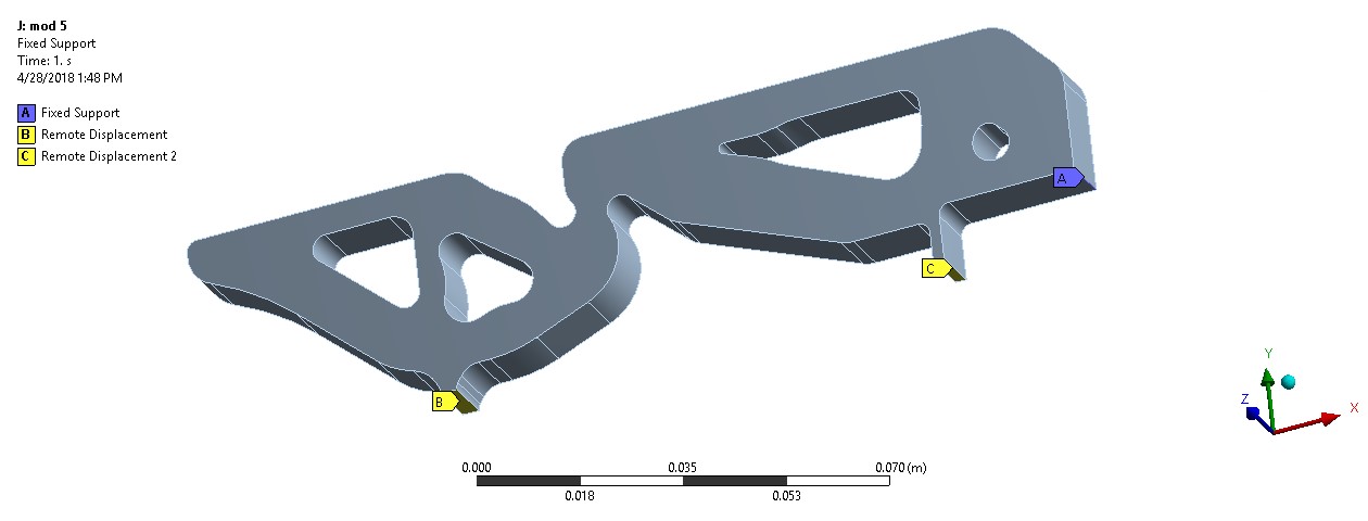
Figure 6: Boundary conditions
Half of the compliant mechanism was simulated taking into account symmetry (Fig.6). A 50 N load was distributed over a 20mm long portion of the mechanism (Fig.7). A fixed boundary condition was applied at the edge where the test block will be gripped. The material properties of FLX9895-DM were used, Young’s modulus of 11 MPa and Poisson’s ratio of 0.4. The linear FEA problem was solved to determine the stresses in the mechanism as well as to predict the amount of force at the output location. Although the properties of the material and the large amount of deformation would make a nonlinear analysis more accurate the linear approximation was used. The very compliant nature of the material made it impossible to get a converged nonlinear result.
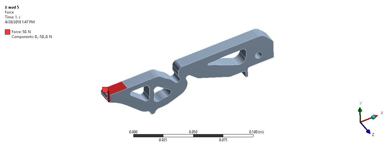
Figure 7: Applied loads
The first analysis was done on the model used to print the second test part (Fig.8). This part was used to attempt to lift a 2 kg mass. Over the course of testing a tear formed at the hinge nearest the input location (Fig.10). This tear formed after about 10 cycles of maximum force being applied. Comparing the location of the tear with the stress analysis it was observed that the location of failure was in tension. For this reason the 1st principal stress was used to determine the weak points of the design. Although the opposite side of the hinge had higher von-Mises stress it did not fail, presumably because the material is weaker in tension than in compression. The maximum 1st principal stress in the mechanism was 20.5 MPa (Fig.11). Based on the testing the design should be improved in the area of the hinge. To reduce the stress in the hinge a circular cut-out was placed tangent to the point of the original hinge. This allowed the stress concentration to be reduced and also maintain the thickness of the hinge, which was a major driver of the mechanical advantage. The thickness of the hinge section near the output was also increased to reduce the stress in that location which was also greater than 15 MPa. With the updates the maximum 1st principal stress in the mechanism is 10 MPa. All three hinges have approximately this amount of stress (Figs.11, 12). This is below the tensile strength of the material of 15 MPa.
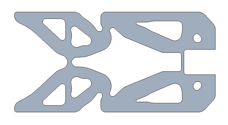
Figure 8: Trial 1
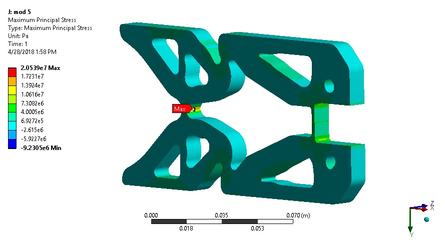
Figure 9: Stress analysis of trial 1
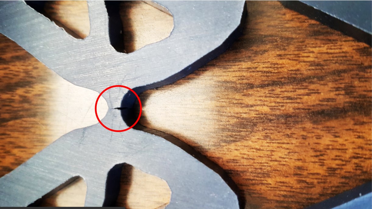
Figure 10: Failure of trial 1
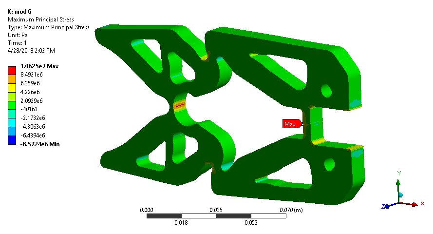
Figure 11: Stress analysis of trial 2
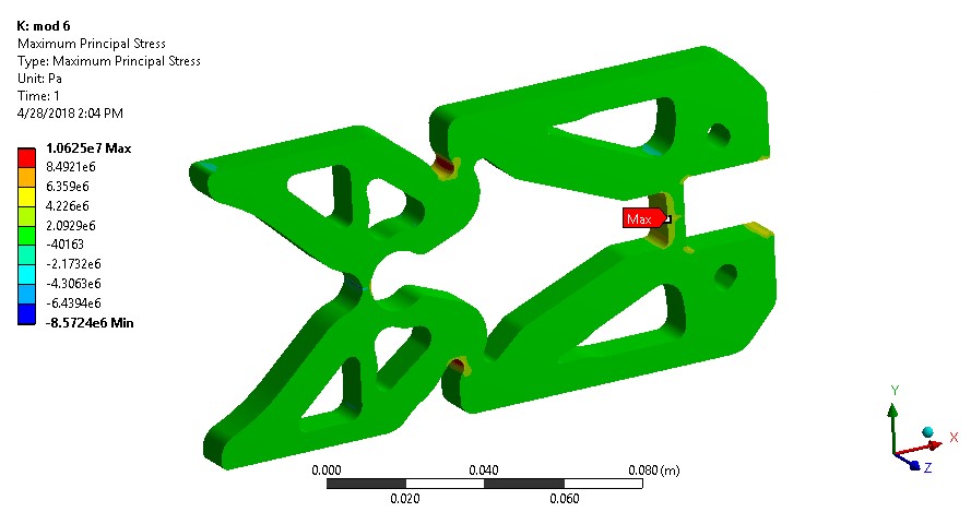
Figure 12: Stress analysis of trial 2
Results and Discussion
A final improvement that was made after testing was to add cut-outs for the fingers of the person using the gripper (Fig.13). When testing, the mechanism often slipped out of the grip of the operator. This should allow the operator to better hold the mechanism rather than just relying on friction to maintain the grasp.
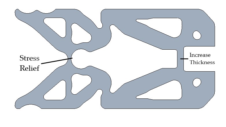
Figure 13: Finalized design
In order to evaluate the performance of the gripper, it is necessary to perform the statics calculation presented in Fig.14. The problem parameters are as follows:
-
Minimum weight to be lifted = 4 lbs. ≈ 18 N
-
Coefficient of friction between gripper and weight (conservative estimate) = 0.3
-
Mechanical advantage of gripper mechanism ≈ 1.2 (obtained from ANSYS FEA)
-
Total force applied by human = 50 N
Therefore, if the operator applies a total force greater than 50 N (includes both ends) the mechanism will be able to lift the minimum weight. Since the stress analysis was carried out for a total force of 100 N (Fig.7), the mechanism is well within the safe operating limits (at least for static loading). Since, the material was shown to have poor fatigue life only a limited number of lifting operations can be performed before failure. Only an empirical result of 10 load cycles were obtained from one test part as a measure of the fatigue life.