Carbon Fiber Reinforced Epoxy Glider
Anthony Klepacki with David Brandyberry
Advisor: Professor Scott White
Abstract
A composite glider is manufactured from a pre-impregnated carbon fiber epoxy system. The glider is originally manufactured from mostly common aerospace grade parts such as high-strength aluminum but due to the weight restrictions and difficulty in tuning the static margin required for stable aerodynamic flight for a hand thrown glider many of the components are remade using carbon fiber prepreg. The glider consists of a main wing that is manufactured using two tools that are CNC machined out of high density closed-cell epoxy tooling board, and then are consolidated to provide a layup that results in a single monolithic part without a distinct parting line. The part is cure in a vacuum bag only oven cure. The stabilizer is manufactured out of a single flat hot-pressed carbon fiber laminated plate. This is then profiled and co-cured using reinforcing plies to avoid mechanical fasteners. Various interface brackets are made of lightweight nylon-12 to assemble the final product. The resulting glider weighs 770g (6.7% reduction over the prototype aluminum-based glider) and flies about 20m.
Introduction
Composite materials are commonly used in the aerospace industry for their superior properties of high specific strength and stiffness. Carbon fiber composites are commonly used in high performance applications due to their increased properties over glass and polymer fiber composites, but they have the disadvantage of being cost prohibitive. Composites also require a larger initial investment for the tooling and additional resources required to manufacture parts, such as large ovens, vacuum systems, and hot presses.
In this project a glider is manufactured out of varying amounts of carbon fiber composite parts to see the effects and tradeoff between using composites and other common aerospace grade materials such as high strength polymers and aluminum alloys. The glider has a simple design consisting of a main wing and stabilizer assembly. Both of these components are mounting to a central mast and are able to have their locations tuned for stable aerodynamic flight when hand thrown.
The critical aerodynamic surface, the main wing, is designed around the Illini Motorsports High Downforce (IMHD) airfoil. This is a purpose designed low Reynolds number, high lift wing, that is robust to surface defects and debris. The wing is manufactured using carbon fiber epoxy pre-preg due to the high volume fraction which results in optimal strength and stiffness properties while remaining light weight. This is layed up using a two-piece clamshell mold with a vacuum bladder and is cured in a vacuum bag only oven cure. The stabilizer is manufactured using a hot-pressed carbon fiber epoxy laminate, profiled using a high-speed diamond saw, and then finally co-cured together. The piece parts are assembled using high-strength and low-weight nylon-12 interface brackets.
Methods and Materials
Materials
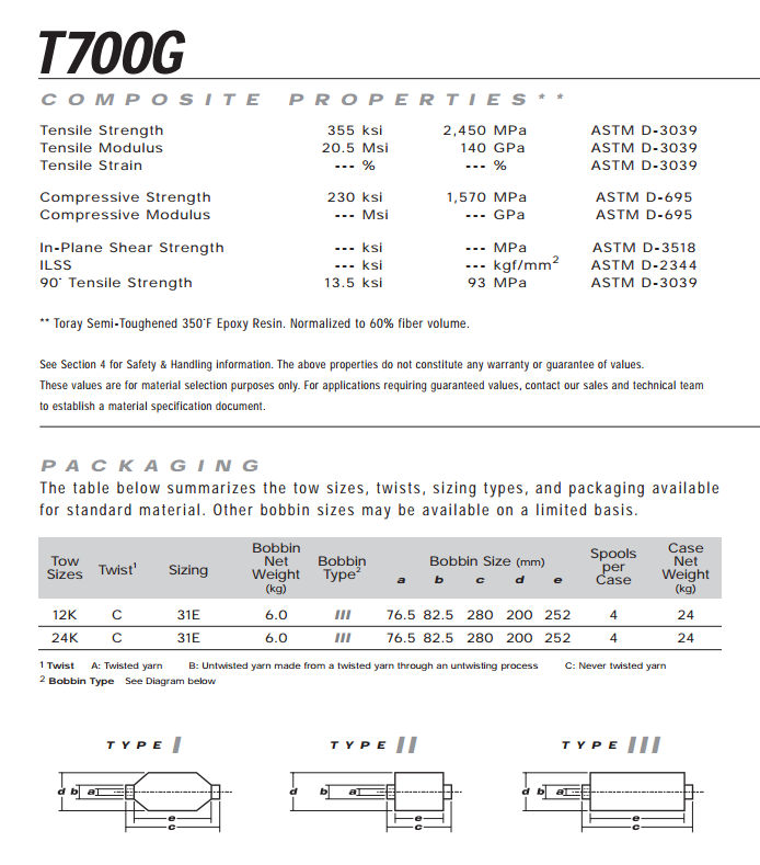
Toray T700g-2510 Carbon Fiber Prepreg
For the composite glider the main composite system that was used was the Toray T700g-2510 pre-impregnated (prepreg) carbon epoxy system. This system is a high modulus fiber (T700g) impregnated with an epoxy (2510) that has a high glass transition temperature (. Due to the stiffness requirements being greater than the strength requirements for the glider the high modulus fiber was favorable to an intermediate modulus fiber with a higher tensile strength. The methods for manufacturing the two main carbon fiber composite components are outlined in the sections below.
The cure cycle for this carbon epoxy prepreg system is based around a vacuum bag only oven cure, where the consolidation pressure is applied by pulling vacuum within the composite layup and thus creating a pressure difference between that and the ambient pressure. Due to the pricing constraints external pressure was not applied inside the autoclave, thus the resulting pressure difference during the cure was held at ~1atm.
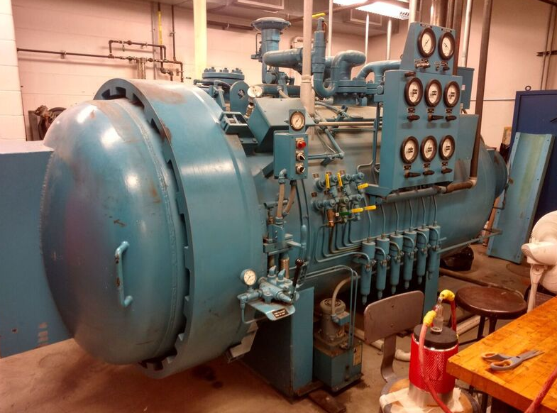
Figure - Autoclave at Tablot Lab
The temperature schedule for the cure is based around two main segments. The first one being the dwell segment, in which the oven temperature is slowly ramped ( to an intermediate temperature of for about 45 minutes. At this point, the epoxy reaches its lowest viscosity, and this allows the consolidation of the prepreg plies as well as further debulking and removal of violates and voids such as air and debris. The reduced viscosity also forms a smooth resin layer on the tooling surface interface which gives a good surface finish on the final part and thus reduces the required post-processing needed for optimal aerodynamic properties.
The second segment of the temperature schedule continues to ramp at the same rate thereafter to the final cure temperature of . The oven stays at this temperature for 3 hours while the curing process takes place, and then ramps down slowly back to room temperature. The ramp rates are required to be low to prevent thermal shock to the tooling materials as well as to mitigate any residual stresses that may form due to rapid cooling. The entire curing schedule is outline below in Figure 2.
Hunstman Renshape 5008 Epoxy Tooling Board
Composite tooling materials are critical to the dimensional accuracy and quality of the final composite product being layed up on them. This is importance is further extended for autoclave and oven curing as the addition of external heat causes expansion and warping of tooling materials, as well as the increased risk of damage from thermal shock. Various types of common aerospace grade composite tooling materials are used in industry and these include metals such as aluminum and invar, but also polymer-based materials such as polyurethane and epoxy-based boards. Metal tooling has the advantage of being robust and reliable for many cures, but certain metals such as aluminum have the disadvantage of having a high coefficient of thermal expansion (CTE). These are typically also cost prohibitive for low volume parts due to the price of the materials and machining required. Polymer based tooling materials have the advantage of being priced lower and the lower density and higher machinability reduce the initial investment needing in creating the tools. These typically are used for prototype tools since the materials degrade under repeated thermal cycling and the quality deteriorates under rough handling.
The composite glider being manufactured is a low volume part and thus an epoxy-based tooling board was chosen for the tooling material. This is a closed-cell foam which results in a good surface finish after machining and does not require additional post processing to achieve the required finish. The epoxy-based tooling material also does not need an additional surface coat to prevent adhesion between the tool and the final composite part. Instead, a liquid polymer release agent is used (Frekote 770-NC). This allows the tool to be machined at nominal dimensions without the need of accounting for the thickness reduction from postprocessing or the additional thickness from surface coats. Finally, the Huntsman Renshape 5008 epoxy-based tooling material has good thermal stability at elevated temperatures and reduces the chances of warping or expansion during cure.
Design and Manufacturing Methods
Airfoil Choice and Design
The airfoil chosen for the main wing of the composite glider is the IMHD airfoil. This airfoil performs well in low Reynolds number regimes of flight with a large coefficient of lift. This airfoil is also robust to surface defects or debris on the wing which is advantageous to a prototype glider since defects in manufacturing may occur as well as debris accumulating on the wing during test flights. The large radius on the leading edge and high camber of the wing also allows for ease of manufacturing with the bladder molding method.
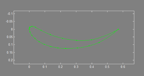
Figure - IMHD airfoil cross-section
Table - Aerodynamic properties of the IMHD airfoil
| [] | [-] | [-] |
|---|---|---|
| 0.0 | -1.661 | 0.02233 |
CNC Machining and Tooling
The dimensional accuracy of the layup tool is critical in achieving a dimensionally accurate final composite part. Due to the complex curves associated with aerodynamic surfaces, such as the airfoil shape for the main wing in this composite glider project, a Computer Numerically Controlled (CNC) router (Shopbot 5-axis CNC router shown below). Three primary machining steps are required to create each of the tools. The first step is a roughing pass to remove the bulk material with a large step over. Secondly, a smaller ball end mill is used to machine the final part surface nominally to the CAD dimensions. Finally, alignment holes are drilled to ensure dimension accuracy between the two halves of the two tools that will be used to layup the main wing.
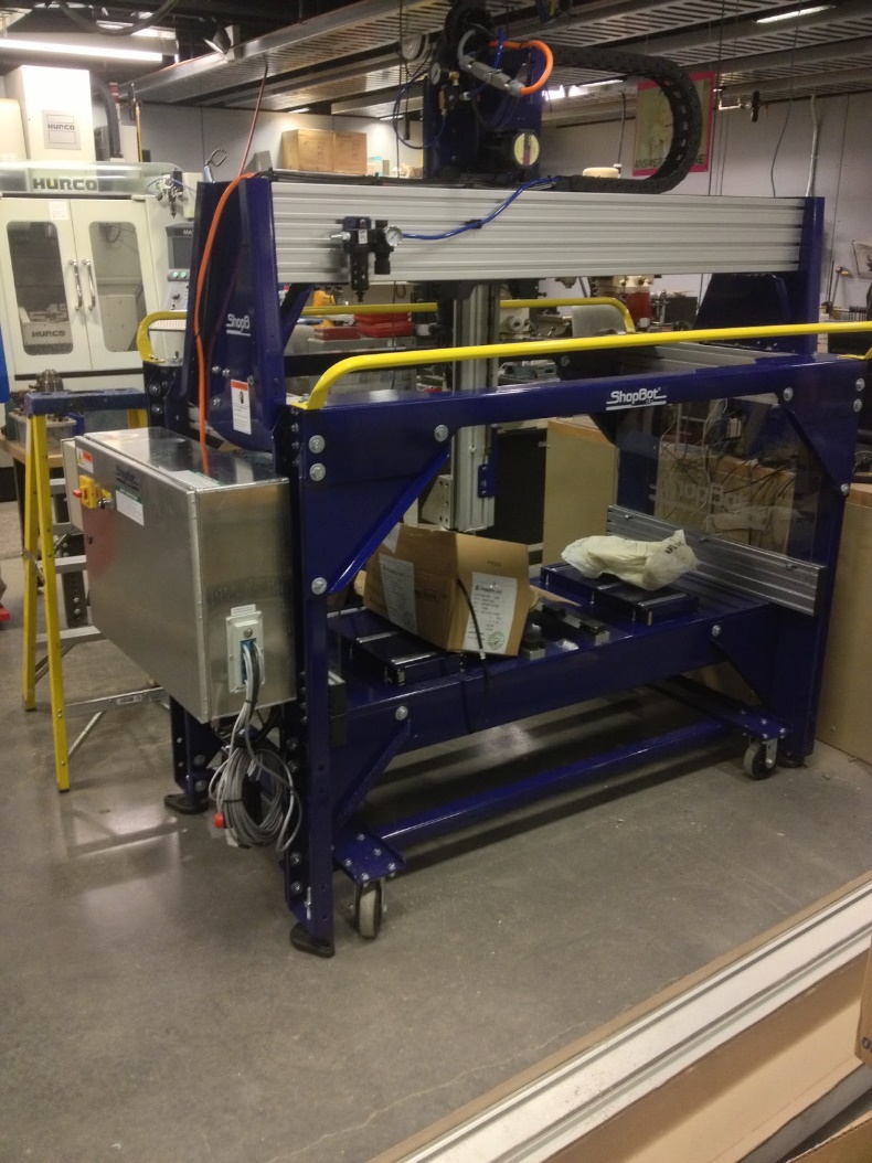
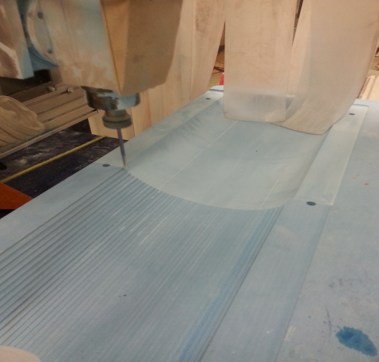
Figure - Shopbot 5-axis CNC router(Left); Machining of the bottom surface of the main wing tool(Right)
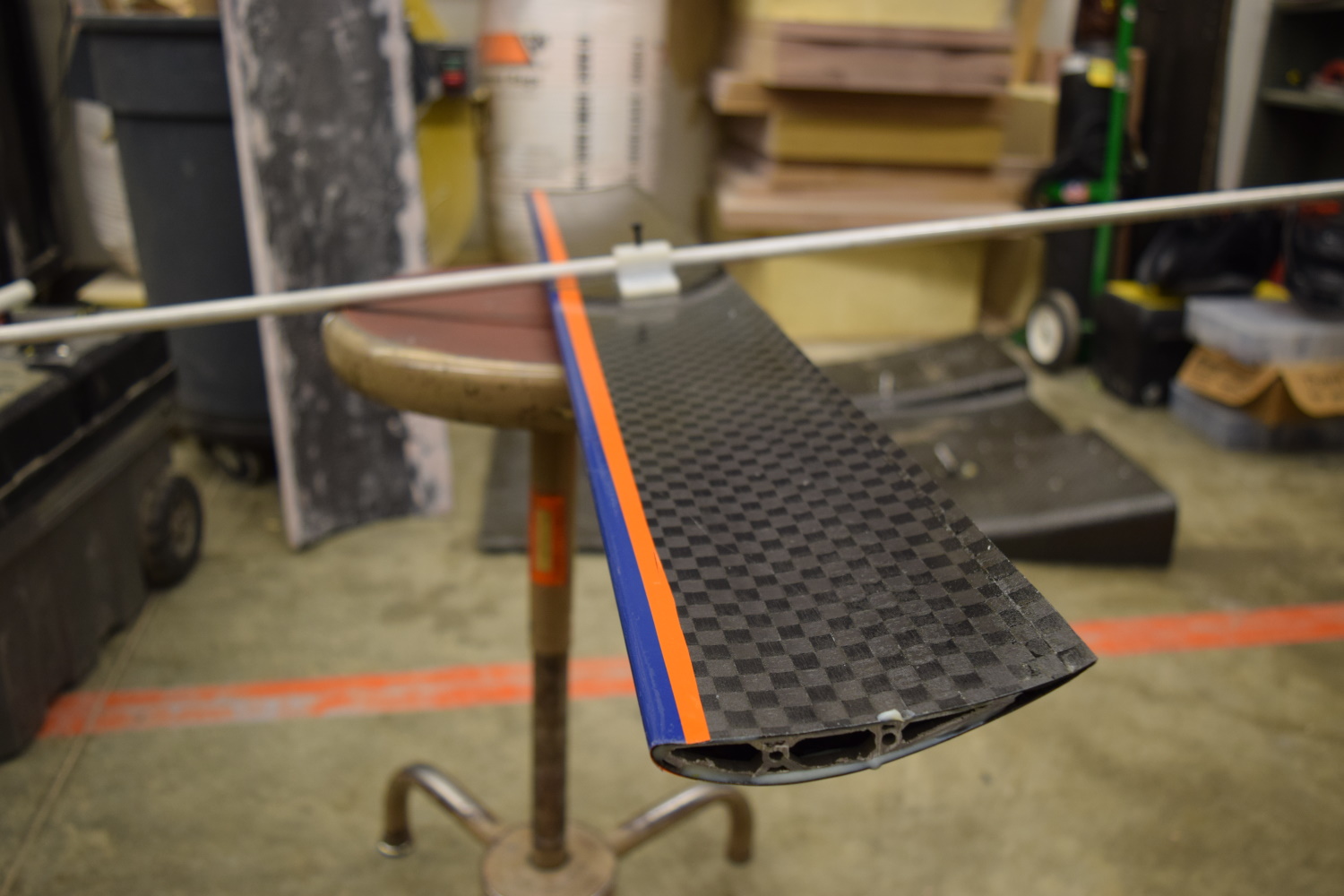
Main Wing Manufacturing
The main wing for this composite glider is manufactured with a standard layup procedure but is modified to include a vacuum bag bladder to pass through the inside of the layup. This allows the exterior of the final part to remain on the tooling surface to ensure dimensional accuracy and good surface finish of the aerodynamical surface. This also allows the final part to be a co-cured combination of the top and bottom halves of the wing which results in a monolithic part that has no parting lines that may affect aerodynamic performance. The center of the bladder is vented to the ambient pressure in the oven, whereas the inside of the entire vacuum bag (bladder and external bag) has vacuum pulled to create a pressure difference that results in the consolidation force for the layup.
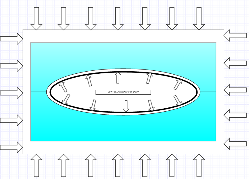
Figure - Diagram of clamshell style bladder mold for wings
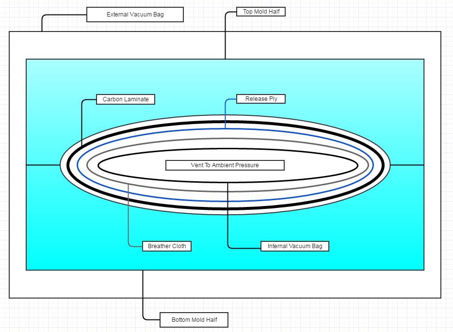
Figure - Internal bagging bladder diagram
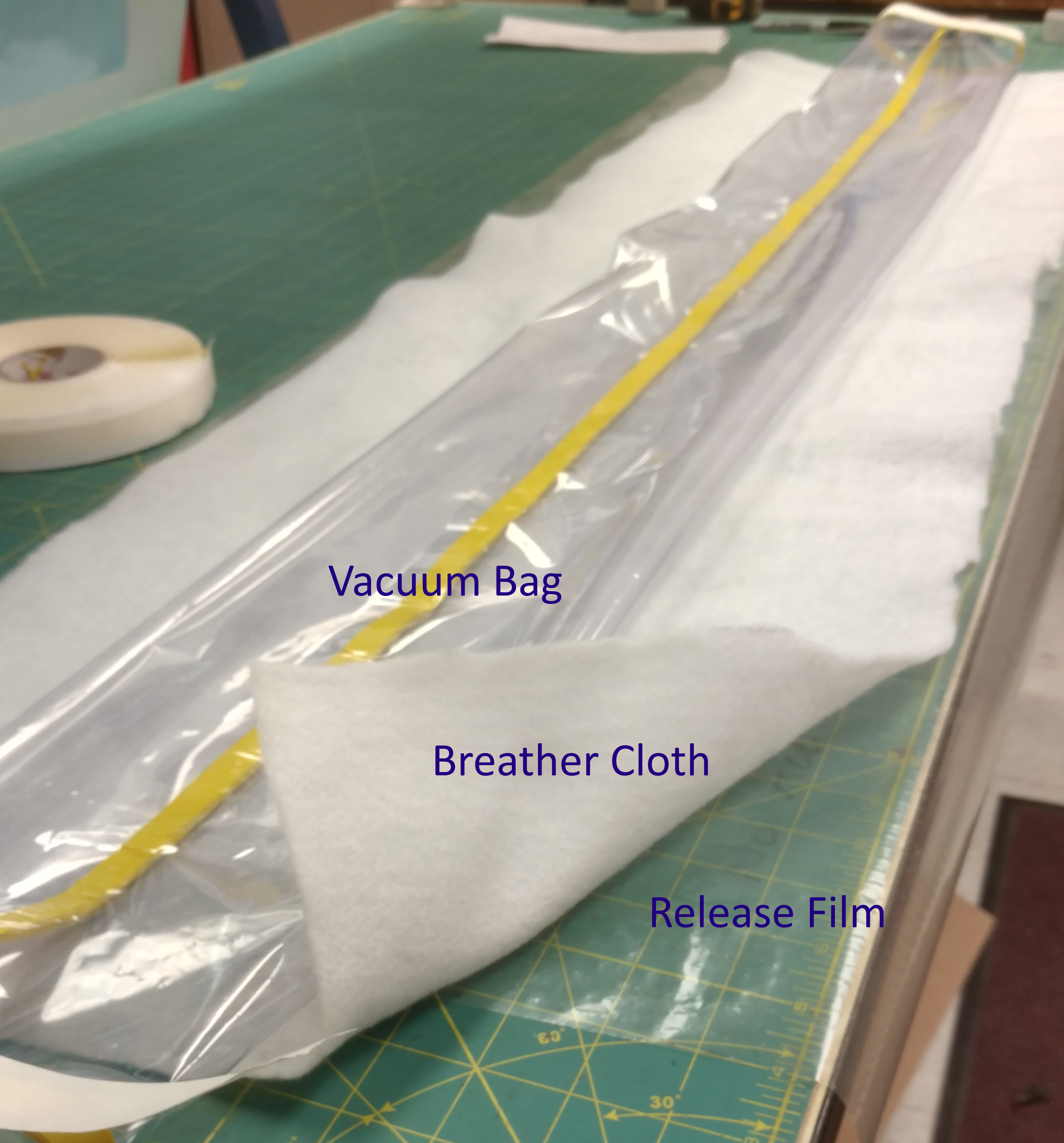
Figure - Assembly of the vacuum bladder
For the layup process, the materials are precut the dimensions required for the ply schedules of the top and bottom layers. Overall three plies are used for the wing. While this results in a thin laminate the required stiffness is achieved from the curvature of the wing, as well as by airfoil shaped aluminum inserts that are bonded into the ends of the main wing. In order to achieve a co-cured part between the two halves an overlap is extended on the outer two plies of the bottom of the airfoil, while the outer two plies of the top half are trimmed back. This overlap is then creased inward when the two tools are assembled together, and the vacuum bladder pushes it against the trimmed portion of the top half. During the curing process these adhere together to create a strong bond which is stronger and more accurate than a mechanical joint that would be required if each half were to be cure individually.
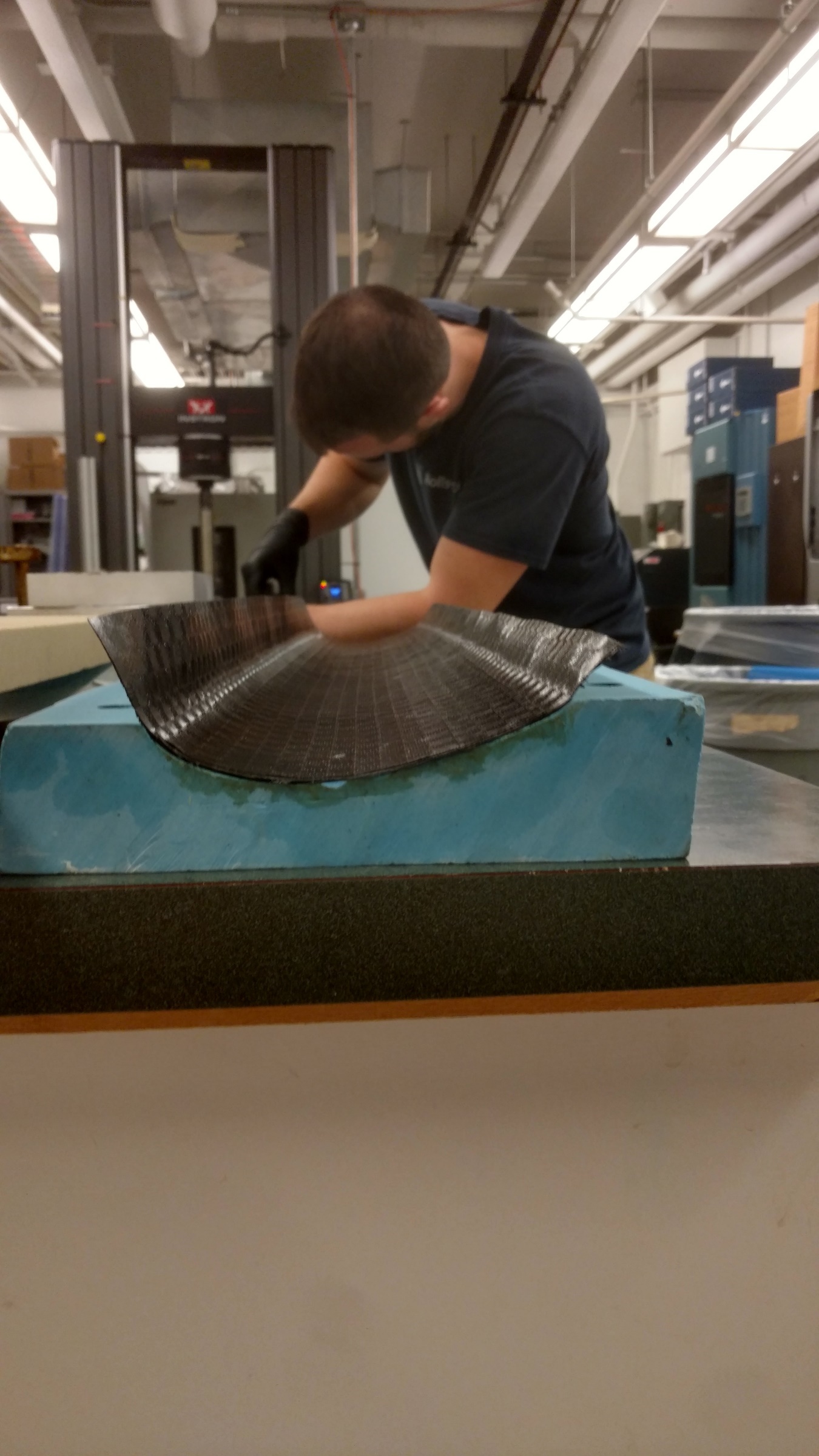
Figure – Overhang detail of the bottom half layup
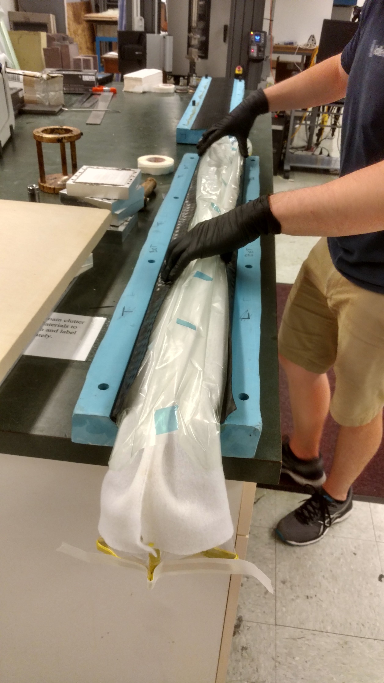
Figure - Assembly of the vacuum bladder into the layup
Once the layup is completed the part is vacuum bagged and the bladder is vented to the pressure. The part is debulked at room temperature under vacuum for an hour and leak tested to ensure a proper vacuum. The cure schedule is performed in accordance with the schedule outlined in the materials and methods section above for the Toray T700g-2510 prepreg system.
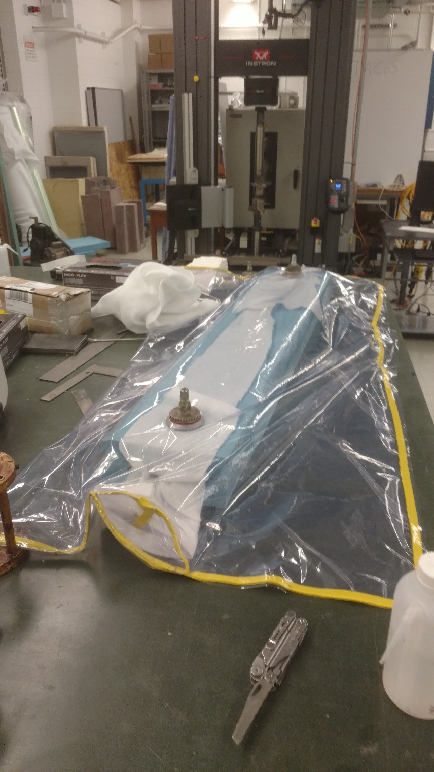
Figure - Final vacuum bag with external vacuum bag, internal bladder, and vacuum ports
After curing the part is demolded and the vacuum bladder is removed from the inside of the wing. Inspection of the breather cloth shows that resin bleed does occur which shows the consolidation occurred during the cure cycle, as well as the vacuum bladder getting into each of the tight crevices of the two halves. This lead to a smooth leading and trailing edge of the main wing and little defects were present. The wing is then cut down to the proper span using a high-speed diamond saw that results in a flat and clean edge at the ends of the wing. Finally, the aluminum inserts are bonded into the inside of the ends of the wing. The surface is sanded and cleaned prior to bonding to promote good adhesion, and the assembly is clamped along the surface to ensure the recommended bond thickness required to maximum strength.
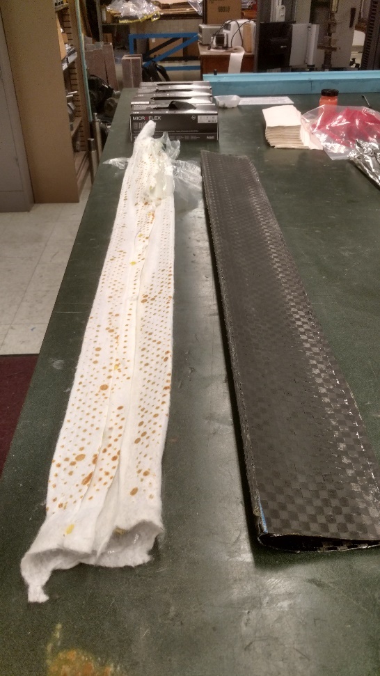
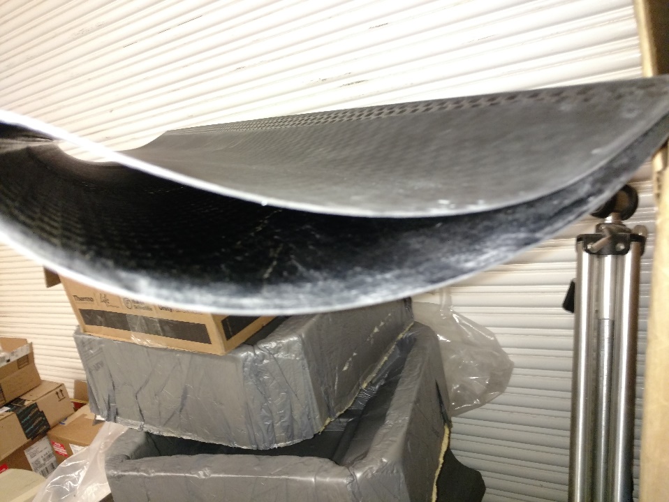
Figure - Demolding process with detail of resin bleed on the breather cloth (left); Final cured part (right)
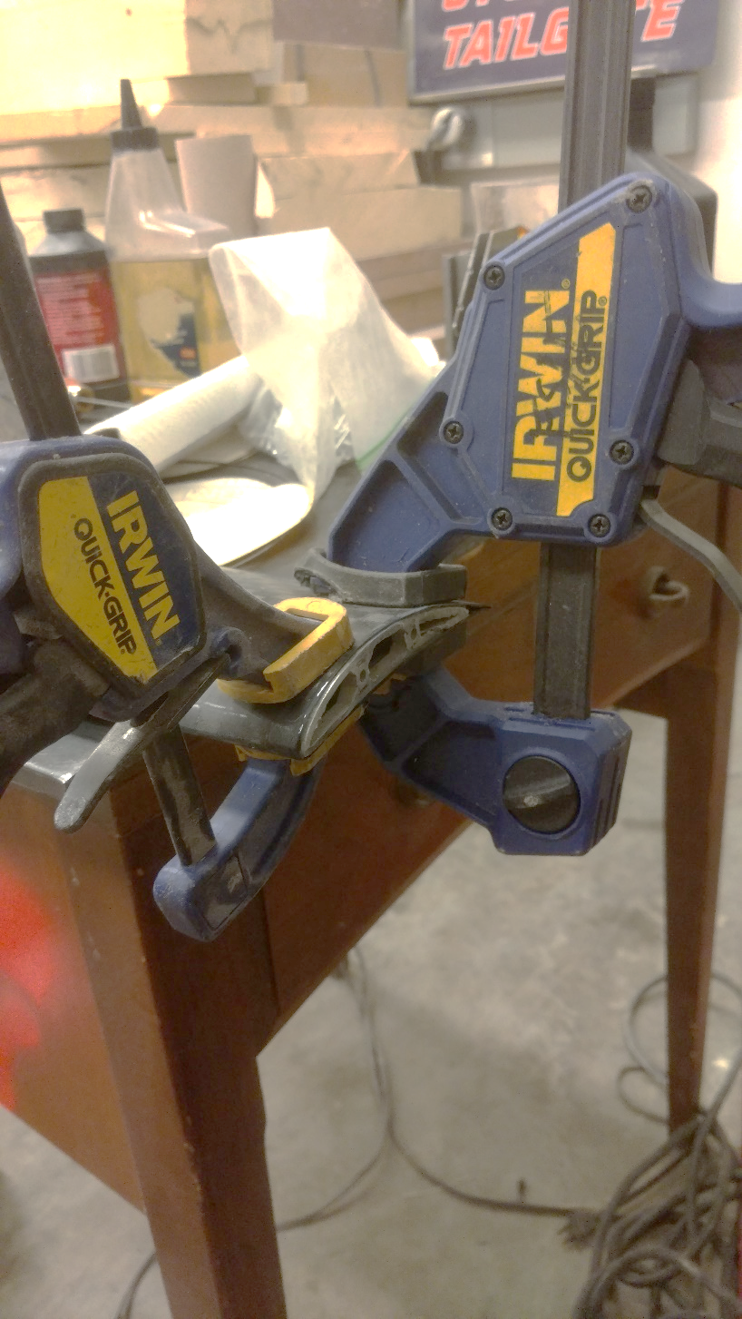
Figure - Bonding process of aluminum inserts into the ends of the main wing
Stabilizer Manufacturing
The manufacturing process of the stabilizer is based around a simpler manufacturing method due to the simpler design. The stabilizer is manufactured out of a flat plate of carbon fiber laminate. The ply schedule is 10 plies of 0-degree woven T700g. The plies are precut to 14”x14” squares and then are layed up in sequence on an aluminum platen that serves at the tool for the layup. Finally, a second platen is placed on top to serve as the second tooling surface. Both of the platens are polished and treated with the same liquid polymer release agent to prevent adhesion between the tools and the final composite part. The hot press imparts the consolidation forces through the use of two hydraulic pistons that press the platens together rather than using a vacuum bag system. The force applied results in a pressure of ~1atm on the layup. The temperature schedule is follows the same schedule as the oven cure cycle.
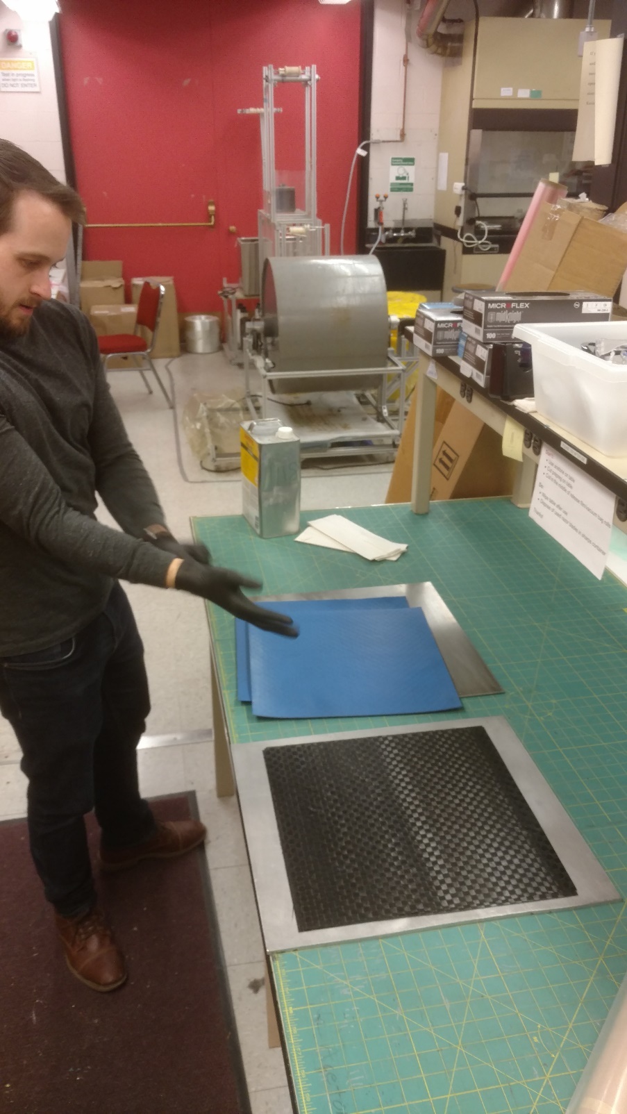
Figure - Precut prepreg plies layed up onto aluminum platens
After the cure the plate is demolded, and the horizontal and vertical stabilizers are marked and cut on the high-speed diamond saw. In order to reduce the amount of relatively heavy mechanical joints and fasteners used on the glider the stabilizer assembly is co-cured together in an oven cure. Small strips of reinforcing carbon fiber prepreg are layed up on the inside corners of the interface of the horizontal and vertical stabilizer and two aluminum blocks are clamped to provide the consolidation force.
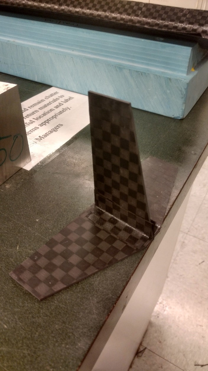
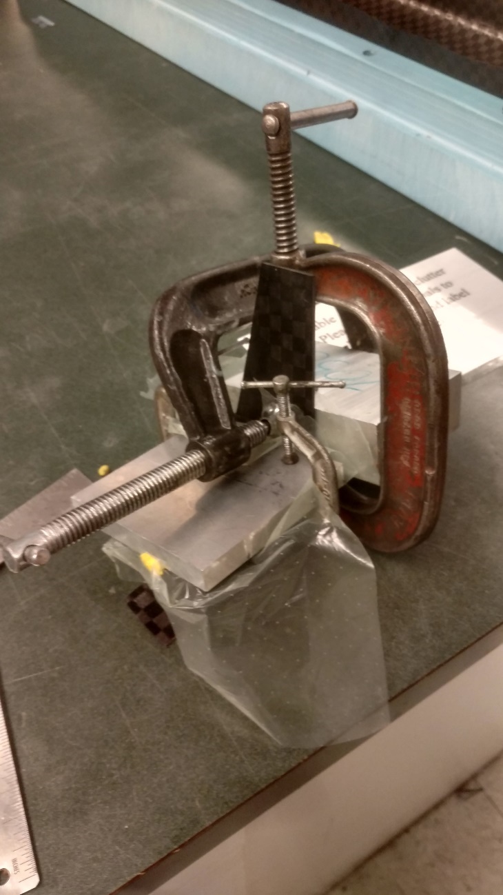
Figure 13 - Reinforcing prepreg strip (left); Clamping assembly (right)
Results and Discussion
Prototype Glider
A prototype was first manufactured to test the overall aerodynamic stability of the glider. This included a carbon fiber main wing as the only composite component as well as an aluminum mast, interface brackets and stabilizer assembly. The carbon fiber main wing had many defects which resulted from poor layup practices and vacuum bagging. The main defects were exterior surfaces of the main wing that did not consolidate to the tooling surface and this resulted in a dimensionally inaccurate final part. Furthermore, the use of aluminum throughout the glider assembly for the prototype resulted in poor weight distribution. A counter weight was required to be placed ahead of the wing to move the center of gravity ( in front of the center of pressure (. The assembly weighed 825g and was difficult to tune the counter weight such that the glider would be able to maintain stable flight.
Table - Prototype manufactured weights
| Prototype [g] | |
|---|---|
| Main Wing Assembly | 385 |
| Rear Stabilizer Assembly | 159 |
| Mast | 116 |
| Counter Weight | 165 |
| Total | 825 |
Final Glider
Due to the defects and heavy weight of the prototype glider a second glider was manufactured with defect and weight reduction as the main objective. In order to reduce defects on the main wing extra care was taken to pre-consolidate the layup prior to vacuum bagging. This was done by carefully placing each of the prepreg plies and then using a roller to remove and air voids that may be trapped between the layers. Secondly, additional provisions were made to ensure that the vacuum bladder was inside the leading and trailing edges. During the vacuum testing the bag was manually shifted into place to ensure that it expanded into these two aerodynamically critical surfaces. Finally, a dwell segment was added to ensure that the plies could align into place and conform to the tooling surface.
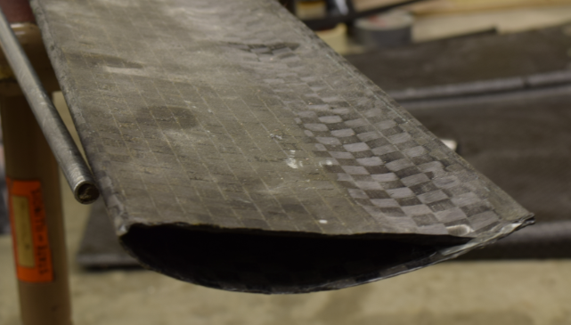
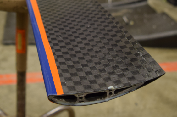
Figure - Prototype with defects (left); Defect free final wing (right)
The second change to reduce the overall weight was to change the stabilizer assembly to fully carbon fiber composites, as compared to aluminum piece parts with mechanical joints. This was replaced with a carbon fiber stabilized that was co-cured together with additional carbon fiber reinforcement. Finally, all of the interface brackets were replaced with Nylon-12 brackets since the loads from flight and impact of landing were not high enough the necessitate metal brackets.
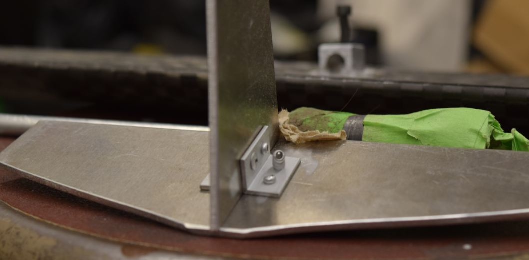
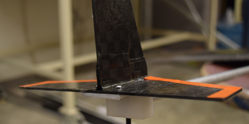
Figure - Prototype aluminum stabilizer with mechanical joints (left); Final co-cured composite stabilizer (right)
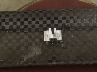
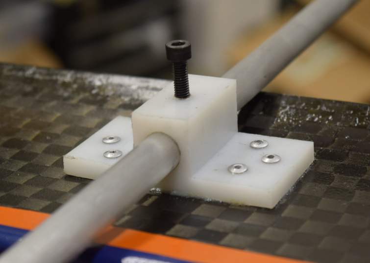
Figure - Prototype aluminum interface brackets (left); Final Nylon-12 interface brackets (right)
In order for the glider to maintain stable flight, the center of gravity () of the entire system needed to be in front of the neutral point (NP) of aerodynamic surfaces. The difference in the locations of these points is known as the static margin (SM). The center of mass can be computed by weighted averaging of the center of mass locations of each component as shown in Table 3. All locations are given relative to the tail end of the aluminum mast.
Table - Final manufactured weights
| Final [g] | [in] | |
|---|---|---|
| Main Wing Assembly | 353 | 23 |
| Rear Stabilizer Assembly | 82 | 0 |
| Mast | 178 | 23 |
| Counter Weight | 157 | 43.5 |
| Total | 770 | 24.7 |
The neutral point of the craft can be calculated by the planform area weighted average of the aerodynamic centers of the two aerodynamic surfaces. This calculation is shown in Table 3. As can be seen here, the static margin of glider is 2 inches, so it should be statically stable. Because of the relatively large static margin, the main wing assembly should be able to be moved forward up to 3.5 inches while maintaining static stability.
Table 3 – Neutral point analysis
| Planform Area [] | \mathbf{AC\ \lbrack in\rbrack} | |
|---|---|---|
| Main Wing Assembly | 189 | 24.1 |
| Rear Stabilizer Assembly | 12.5 | 0.4 |
| Total | 22.7 |
The move to a composite stabilizer assembly and the addition of nylon brackets over aluminum led to the ability to use a lighter counterweight as well as making it easier to balance with the wing near the center of the mast. Overall each of the components reduced in weight, but the mast increased in weight to achieved higher stiffness, as well as to handle impact on landing. Table 4 shows that we had a 6.7% reduction in overall weight between the prototype and the final, however, this could be improved by using a thinner mast or a differently balanced system to reduce the need for a counterweight.
Table - Weight comparison between prototype and final gliders
| Prototype [g] | Final [g] | Delta Weight | % Change | |
|---|---|---|---|---|
| Main Wing Assembly | 385 | 353 | -32 | -8.3% |
| Rear Stabilizer Assembly | 159 | 82 | -77 | -48.4% |
| Mast | 116 | 178 | 62 | 53.4% |
| Counter Weight | 165 | 157 | -8 | -4.8% |
| Total | 825 | 770 | -55 | -6.7% |
Conclusion
The final composite glider was able to perform well in hand-thrown flight as compared to the aluminum-based glider. This was mostly due to the reduction of the weight of the stabilizer assembly which allowed for easier tuning of the overall aerodynamic properties of the glider. Secondly, the reduced number of defects on the final glider allowed for maximum aerodynamic performance of the main wing.
Further work to reduce the defects on the main wing would include to change the amount of overhand that is required to co-cure the top and bottom halves of the wing. Since this material is difficult to conform to a tight radius, as well as to consolidate together, a change in these lengths may make it easier for the vacuum bladder to push the layup toward the leading-edge sections of the molds. A longer room temperature debulk could also help in removing voids prior to the increasing the temperature during the cure which has the potential to increase the volume of the voids. Finally, a change in the bladder material could improve the efficacy of the bladder overall. Currently a vacuum bladder is used, but a changed to a solid silicon preformed bladder could help by acting first as a mandrel to create a single layup without the need for two individual half layups, but also to provide a more even expansion for the consolidation phase since silicon has a higher CTE than the carbon fiber and tooling material.
For the glider assembly changes defects occurred from the co-curing which results in a sub-optimal structure that is prone to damage. This was due to the lack of a vacuum bag being used. Proper vacuum bagging or a better clamping preform would allow for a better co-cure joint to be formed. Finally, the nylon-12 interface brackets could be reduced in weight further by making them out of carbo fiber. This would require a higher initial investment in materials and resources since molds would need to be created, but this would be a tradeoff for a reduction in mass.
-
References
-
Appendices
Material Datasheets
Toray T700G Datasheets
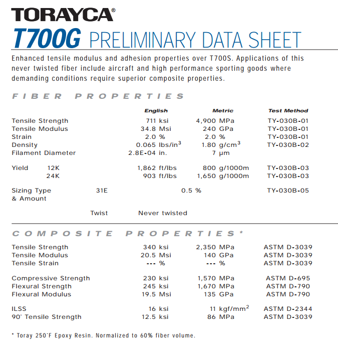
Figure - Toray T700G Datasheet
Tooling Materials
Huntsman Renshape 5008 Epoxy Board
-
Used on multiple manufacturing run parts such as wing elements
-
High closed cell content for smooth finish after post processing
-
High thermal stability at cure temperature for better dimensional accuracy
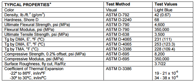
Figure - Huntsman Renshape 5008 Properties