Aircraft Design Project - Structural Subsystem
Anthony Klepacki
Advisor: Professor Steven J. D’Urso
Primary Structures Design and Analysis

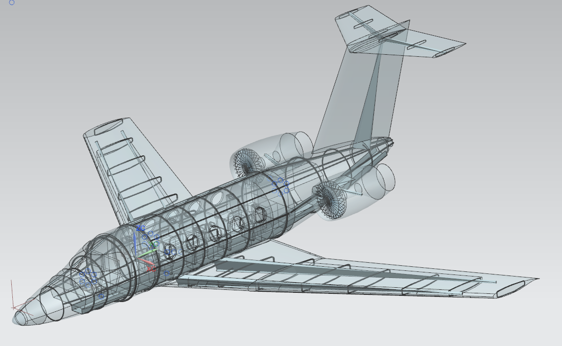
Figure 1 - Complete Structures CAD Assembly
Introduction
The primary structures for the family of small business aircraft that we are designing compose all the major and critical load bearing structures located throughout the plane. These included all the wing primary and secondary structures, the fuselage skin, longerons and stringers, as well as any associated structures for the forward and aft cockpit and empennage. A common methodology was employed for sizing, designing and analyzing each of these structures with three primary constraints. The first major constraint employed was that aircrafts being designed were part of a family of planes, and thus, it was necessitated that a minimum of 70 percent commonality between the two planes was achieved. The second primary constraint was weight consciousness. This was realized through proper sizing of components to the required safety margin specified by FAR-21. The third primary constraint was that the first aircraft in the family was required to be in production and flight within four years. This necessitated a design for manufacturability (DFM) oriented design process in which components and materials were chosen such that new methods of manufacturing and assembly were not need with the expedited schedule.
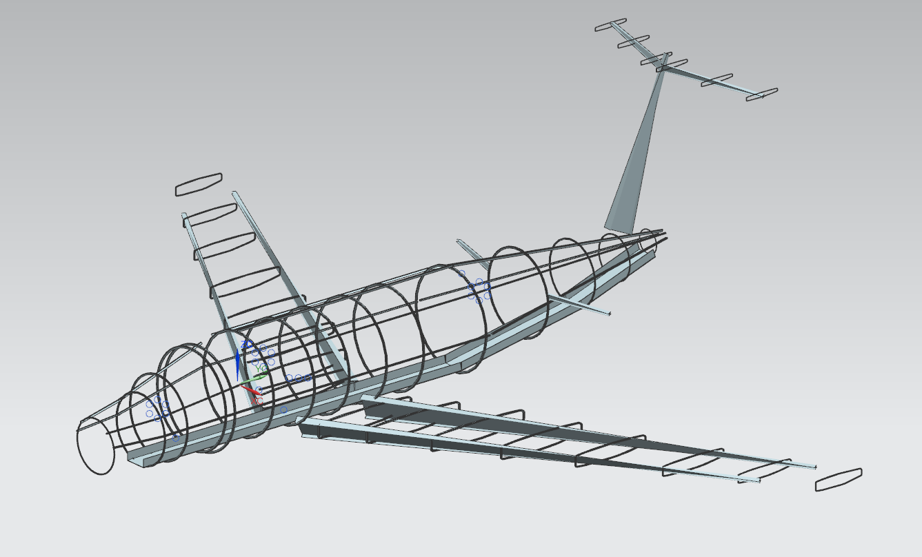
Figure 2 - Isometric View of all Primary Structures

Figure 3 - Top View of all Primary Structures

Figure 4 – Side View of all Primary Structures
The primary material chosen for the structures of this aircraft was an aerospace-certified alloy, Aluminum 7075-T6. The specific alloy and temper gives extremely high material properties in both strength and stiffness, while providing a high specific strength [1]. Another advantage of this material is that the processing, machinability and manufacturing of this material has been widely used in the aerospace industry and thus is easy to source and implement, all while being very cost-effective.

Figure - Aerospace Certified Material Properties and Allowables for AL 7075-T6
The goal and constraint of being weight conscious was achieved by identifying the major loading scenario for each of the primary structures on the aircraft, choosing the optimal geometry and ultimately sizing the part for the minimum allowable margin of safety (M.O.S) as specified by the FAR-21 document, which for all primary structures is. Common load bearing geometries such as I-beams and C-channels were widely used throughout the aircraft structures due to their exceptional strength and stiffness.
Wing Structures
Wing Primary Structures
The primary structures for the main wing of the aircraft are the two beams at the forward and aft part of wing. The major loading cases that the beams are sized to correspond to lift and drag loading, and the maximum values for the entire mission profile are chosen to be the limiting case, as shown in Table 1 below.
Table - Limited load cases for wing primary structures
| Wing Primary Structures Limited Load Cases | |
|---|---|
| Lift | 34882 lbf at landing |
| Drag | 3505 lbf at landing |
An I-beam geometry was chosen for both the forward and aft beams running along the leading and trailing edges of the wing. The reasons for choosing this geometry is three-fold. The first reason is that the I-beam is designed to take large bending loadings in the direction of the main web. Bending is the critical failure mode of the wings at the root of the wing-fuselage interface due to the moment induced by the lift force. The beam can also take bending loads in the perpendicular direction though the top and bottom skins, which will take the bending loads induced by drag of the aircraft. The second reason is that the beams have a high degree of optimal sizing. This is due to the various variable dimensions, as shown in Figure 2, that can all be independently changed so that the smallest amount of material is used while maintaining adequate strength and stiffness. The final reason for the chosen geometry is that it is relatively uniform, allows for ease of manufacturing through extrusion or forging, and can easily be made of the aluminum alloy chosen.

Figure - Primary I-beam dimensions [2]
The I-beam was sized for maximum bending induced at the wing root using the fundamental bending stress formula derived from solid mechanics:
Equation .
The moment is idealized as a point load at the span-wise center of pressure (CP), with a moment arm from the CP to the wing root. Using the linearity of bending stress span-wise down the wing, it is tapered linearly to the wing-tip with a ratio identical to the aerodynamic taper ratio. This allows for optimal sizing as compared to a uniformly dimensioned wing beam. The final and dimensionally sized geometry is shown below in Figure 4. The dimensions were chosen using an automated and iterative solver in Microsoft Excel using the ‘Goal Seek’ and ‘Solver’ features, where the variables were the four critical beam dimensions (see Figure 2), and the mass was minimized while always keeping a . Due to the maximum drag value being an order of magnitude lower than the maximum lift force, the moment induced by lift was always the stress limiting loading scenario, and thus the beam has a relatively large aspect ratio in the vertical Z-direction.
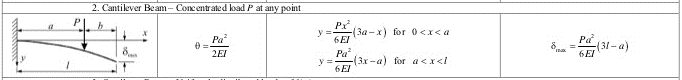
Figure - Stresses and deflections of a cantilevered beam with a point load [2]

Figure - Final Primary Wing Beam Dimensions
Wing Secondary Structures
The secondary structures of the wing are composed of the outer skin and the internal ribs placed span-wise along the wing. These provide span-wise stiffness for the wing and enough strength to prevent any pressure induced deflection and failure created by the fuel in the wings. The major loading cases for the secondary structures are the hoop stresses induced the pressure differential created between maximum fuel pressure and ambient atmospheric conditions at service ceiling flight. The skin thickness is to be chosen to match the skin thickness of the fuselage to homologate manufacturing processes across the aircraft, and due to the max pressure differential being less than that of the fuselage to atmosphere at equivalent conditions.
The second component of the secondary structures are the wing ribs and these aid in increasing stiffness in the span-wise direction, holding the two primary beams in place, supporting the wing skins, and providing an area where fuel could be stored.. Eight ribs are chosen to be implemented per wing, which provides an inter-rib space of ~38 inches. The cross section for the perimeter of the rib, is chosen to be a T-beam so that the flat face can lies flat with the skin while still being stiffened by the web of the beam. A CAD model of this is shown below in Figure 8
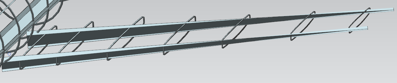
Figure 9 - Detailed View of Wing Primary and Secondary Structures
Fuselage Structures
Longerons and floor
The main components of the fuselage structure are the floor beam and the longerons that run along the length of the entire plane. The main load bearing section is the fuselage section, while has a set of five uniform T-beams along the top half of the fuselage as shown in Figure 5 below, and a larger single C-channel running along the floor of the entire plane, from the cockpit, all the way through to the empennage.
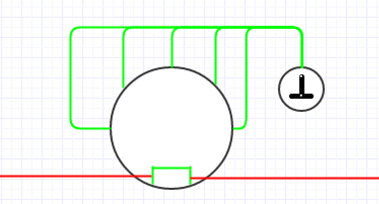
Figure - Upper longerons (including T-beam cross section) and main floor beam
The main loads in the fuselage are the axial loads induced by the pressure different of the pressurized cabin relative to the atmospheric pressure at the service ceiling conditions. We derive this the limit load for axial stress by the approximation of a pressure vessel, as shown below:
Equation
The second primary loading on the fuselage is the bending of the fuselage, which can be approximated to be a length-wise beam, with free support on each of the ends, corresponding to the forward and aft limits of the aircraft, with a point load being applied at the center of the main wings with an amplitude equal to that of max lift at landing. The free-body diagram and corresponding solids mechanics equations can be seen in Figure 6 below.
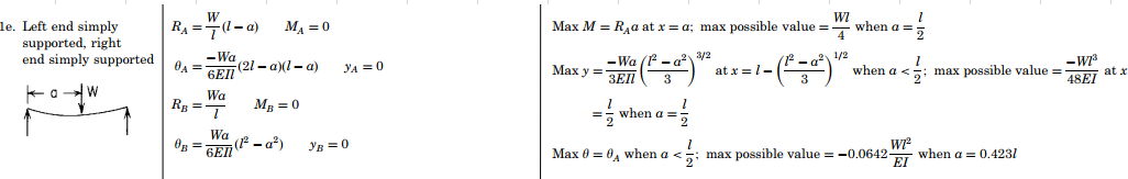
Figure - Fuselage Bending diagram [2]
The beams were designed with two considerations in mind. First, the axial loads were designed to be taken purely by the longerons, thus leading to a conservative margin of safety. The cross-sectional area of the sum of all five beams was derived using the same iterative and automated solver, like the wing primary structures design, and an initial aspect ratio of was chosen for the T-beam. After this, the dimensions of the floor C-channel were chosen. The strong dimensions, corresponding to ‘Dim B’ and ‘Dim H’ in Figure 7, were constrained by the configuration group as part of the main internal floor geometry, but we are still left with the wall thicknesses as a variable. The area moment of intertia of the ‘fuselage beam’ is approximated using the parallel axis theorem and linear superposition, with an approximated neutral axis running through the C-channel since .

Figure - Primary C-channel dimensions and geometry
The final dimensions for each of the beams are tabulated below, as well as maximum longitudinal deflections set at . The margins of safety for the longerons are set at but since they are designed to support the full axial load, the floor beam ultimately increases the effect margin of safety for the overall axial support structure.
Table - Primary Longeron Dimensions
| Longeron Parameters | ||
|---|---|---|
| B | 1 | [in] |
| b | 0.25 | [in] |
| H | 1.25 | [in] |
| h | 0.25 | [in] |
Table - Primary Floor Beam Dimensions
| Floor Parameters | ||
|---|---|---|
| B | 6 | [in] |
| b | 0.3 | [in] |
| H | 16 | [in] |
| h | 0.3 | [in] |
| Fuselage Margins and Limit Load Deflections | ||
| \text{M.O.}S_{\text{longerons}} | 0.5 | |
| \delta_{\max} | -0.04 inches (at longitudinal limits under max lift at landing) |
Stringers and Skin
The second primary section of the fuselage structures are the stringers and skin. The primary intent of the stringers is to provide longitudinal bending stiffness, when coupled with the longerons and floor, and to interface with other primary structures such as the wing, window, and tail section interfaces. The radial sections are designed in the same twofold manner as the length-wise sections. The skin is designed to support the maximum hoop stress induced by the limiting pressure differential, but these are also reinforced by stringers which are spaced to support other interfacing primary structures. A simplified systems-level diagram is shown below in Figure 8.
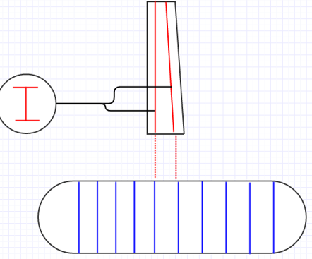
Figure - Stringer spacing diagram and interfaces
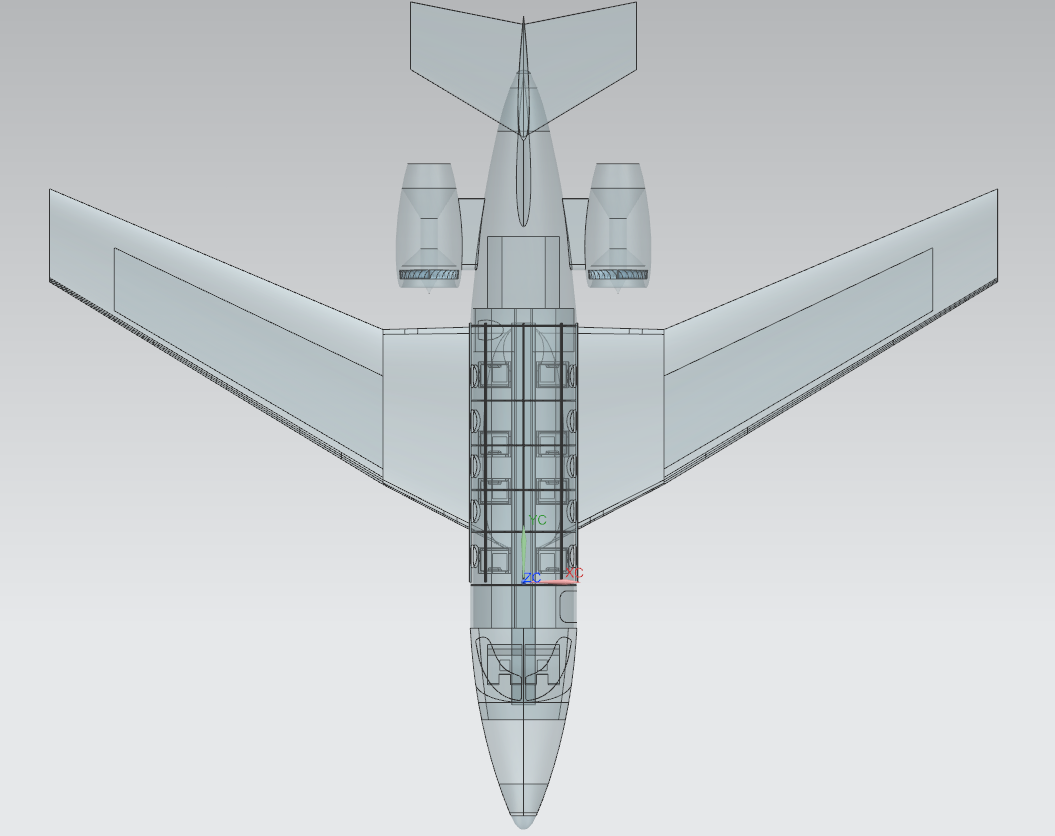
Figure 14 - Top View of Fuselage Structures

Figure 15 - Isometric View of Fuselage Structures

Figure 16 - Detailed View of Wing Spar and Fuselage Interfaces
The skin is designed to support hoop stress induced by the pressure difference at service ceiling conditions. This is calculated through Equation 3. Using the iterative and automated solver coupled with a constrained , a skin thickness of was derived. The thickness is increased to due to unimplemented stress concentrators that result from joint interfaces. This also aids in the primary goal of designing towards ease of manufacturing by specifying a common gauge of sheet aluminum.
Equation .
The stringer was sized to support loads at interfaces rather than being designed as a critical loading bearing structures needing to make a minimum M.O.S. The spacing of the stringers is variable along the length of the fuselage, and primarily placed at the interfaces where the wing primary beams connect, as well as supporting windows at locations of seats per the configuration group’s requirements. The dimensions of the T-beam used in the stringers are identical to the longerons, such that tooling and manufacturing costs are kept low, as well as allowing commonality between the two aircraft in the family. The dimensions can be found in Table 2 and a systems-level of all the primary and secondary fuselage structures in Figure 15 above.
Cockpit and Empennage Structures
The structures for the cockpit follow the same design and analysis regime as for the fuselage. Using the linearity and superposition relationships of Equations 1,2, and 3, we can appropriately size and scale the longerons and stringers proportional to the diameters of the fuselage and other load-bearing structures. The cross-sections, geometries, and materials of each corresponding beam and structure are kept identical to the fuselage, resulting in primary dimensions being the only variables. The sole exception to this constraint and design methodology is that the forward part of the floor beam is kept identical to the fuselage dimensions, but the aft section is tapered appropriately. This is due to the cockpit configuration being analogous to the passenger compartment.
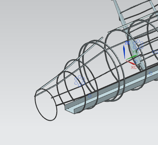
Figure 17 - Detailed Isometric View of Cockpit Primary and Secondary Structures
The spacing of stringers in the cockpit is constrained to a maximum inter-stringer distance of 36 inches. Locations of the stringers are chosen to support primary components of the cockpit, such as the forward and aft supports of the main forward windows, front bulkhead, and the interfaces to the main fuselage section. The same design methodology is implemented for the spacing and placement of the stringers in the empennage with intended supports being for the vertical tail and horizontal stabilizers.

Figure - Stringer Locations for Cockpit, Fuselage, and Empennage
Vertical Tail and Horizontal Stabilizer Structures
To decrease cost, expedite the manufacturing and tooling timelines, and to aid in structures commonality, the tail and stabilizer structures are derived from the primary and secondary wing structures. Each will have a single, rather than double, beam implemented and these will interface directly to the empennage longerons and stringers. Sections will be cut from the tapered ends of the wing beams and from the rib sections. This is attainable due to the lift and drag forces being lesser than those of the main wings and the stresses are lesser due to the linearity of Equation 1. The skins are also kept uniform and identical to that of the fuselage and main wings to decrease tooling and resource costs, as well as having common manufacturing practices throughout a wide variety of sections of each aircraft variant.

Figure 19 - Tail Section Primary and Secondary Structures
Primary Structures Commonality Design
As per the constraints of 70 percent structures and configuration commonality between the family of aircraft, each of the primary structures have been designed to limit loads corresponding to the 8-seat aircraft. The 6-seat aircraft will use the same configuration of wing structures, longerons, and floor and cockpit/empennage structures. The main difference between the two aircraft variations is that the 6-seat aircraft will have one less fuselage stringer section which will eliminate a window support and corresponding row of seats. This methodology of implementing a high degree of structures commonality will allow tooling and manufacturing for the aircraft to be created from a single set of processes with slight length-wise dimensional changes being needed only for the fuselage longerons. The fuselage will be manufactured in two sections, one being forward of the wing centerline and the other being after of the centerline. For the 8-seat variant there will be an additional stringer section manufactured independently and joined between the two primary sections giving the additional length and seating configuration.
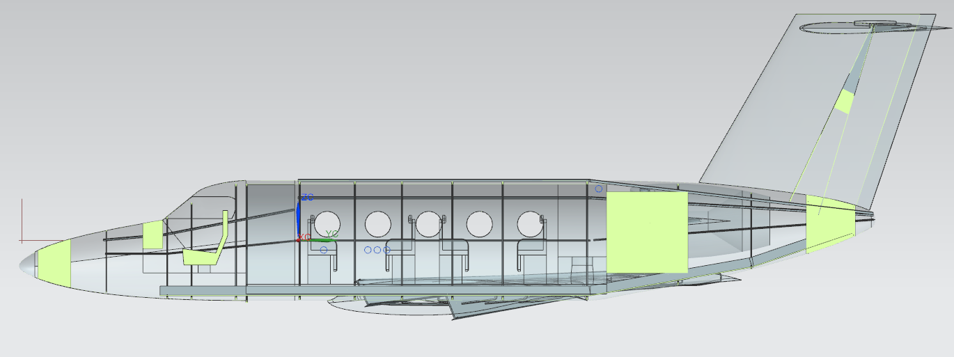
Figure 20 - Section View of Primary Structures Design and Integration within Full Aircraft Assembly
Primary Structures Summary and Weights Analysis
Weight consciousness was one of the primary objectives and constraints, along with an expedited design and manufacturing timeline and commonality between aircraft variants. Using the independently design and created iterative solver each section was designed to a set of hard constraints, such as dimensions specified by the configuration group, as well as the hitting the minimum mandated margin of safety. Examples of the user-created tool are shown below in Figure 9 and Figure 10. The tool features an overview page where primary input parameters can be specified with automatic feedback for safety margins and weights. More detailed analysis pages are also included such that parameters for certain structures can be independently tuned and verified. This leads to optimal geometries and efficient structures, and ultimately resulted in a low structural weight for the aircraft. A table of structural weight for the aircraft weight is shown below in Table 4, along with critical margins of safety for primary load bearing structures.
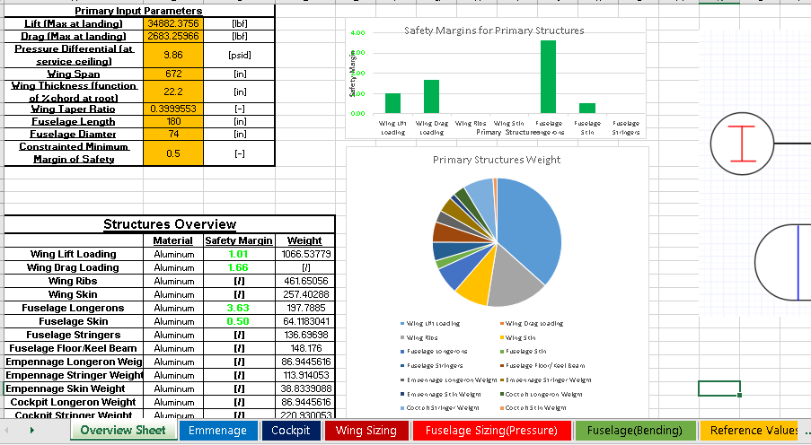
Figure - User-created Iterative Solver and Automated Design Tool Input Screen
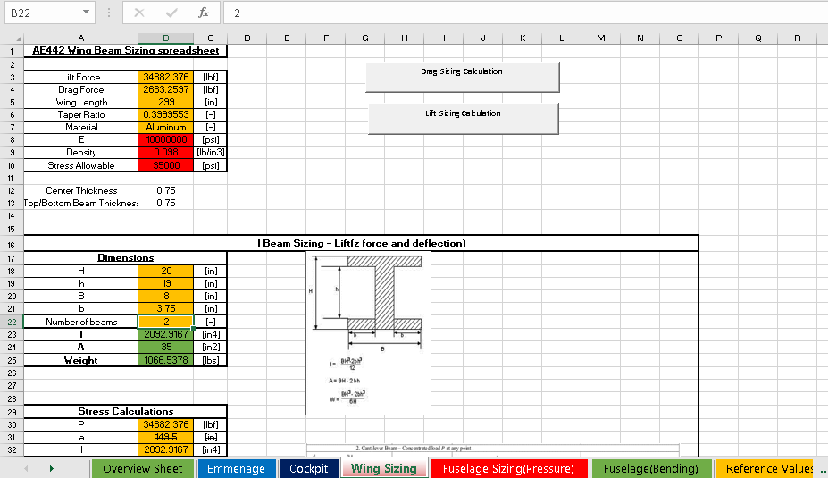
Figure - User-created Iterative Solver and Automated Design Tool Detailed Analysis Screen
Table - Tabulated Weights and Margins of Safety for all Primary and Secondary Structures
| Structures Overview | |||
|---|---|---|---|
| Material | Safety Margin | Weight | |
| Wing Lift Loading | Aluminum | 1.01 | 1066.537795 |
| Wing Drag Loading | Aluminum | 1.66 | [/] |
| Wing Ribs | Aluminum | [/] | 461.65056 |
| Wing Skin | Aluminum | [/] | 257.40288 |
| Fuselage Longerons | Aluminum | 3.63 | 197.7885 |
| Fuselage Skin | Aluminum | 0.50 | 64.1183041 |
| Fuselage Stringers | Aluminum | [/] | 136.6969795 |
| Fuselage Floor/Keel Beam | Aluminum | [/] | 148.176 |
| Empennage Longeron Weight | Aluminum | [/] | 86.94456164 |
| Empennage Stringer Weight | Aluminum | [/] | 113.9140534 |
| Empennage Skin Weight | Aluminum | [/] | 38.8339088 |
| Cockpit Longeron Weight | Aluminum | [/] | 86.94456164 |
| Cockpit Stringer Weight | Aluminum | [/] | 220.9300534 |
| Cockpit Skin Weight | Aluminum | [/] | 29.14913681 |
| Total | [-] | [-] | 2572.063542 |
This is only a partial list of weights as it does not include fasteners, joints interfaces, gussets and stiffeners. However, each section is representative of the distribution of weights for each section of the aircraft, and the distribution of weights relative to each other can be seen in Figure 11. The weights shown are for the 8-seat variant but the 6-seat variant would be similar, with a reduction in weight only decreased by the weight of a single fuselage stringer section and the decreased length of the corresponding longeron, floor section, and outside skin.
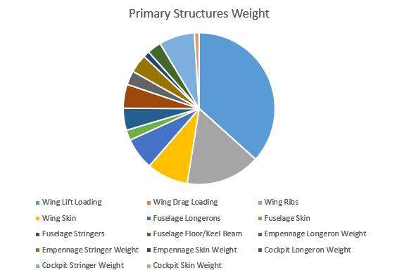
Figure - Relative Weight Distribution for Primary and Secondary Structures
References
-
Metals Handbook, Vol.2 - Properties and Selection: Nonferrous Alloys and Special-Purpose Materials, ASM International 10th Ed. 1990.
-
Roark, R. J., Young, W. C., & Budynas, R. G. (2002). Roark’s formulas for stress and strain. New York: McGraw-Hill.
Aircraft Design Project - All Subsystems
Anthony Klepacki with Aarav Balsu, Patchara Choakpichitchai, Kevin Dvorak, Kevin MacDuff, Liam McHugh, Alicia Qiu, Martynas Vasiliauskas, and Hyung Woo You
Advisor: Professor Steven J. D’Urso
This project was part of a larger aircraft design project. The PCR presentation from the project is shown below in PDF form.